Click the main image to view the original. Select a thumbnail to switch.1 / 35
15W Qi Wireless Charging Transmitter Module Type-C Input 4-10mm Gap Ultra-Slim Coil and Control Board
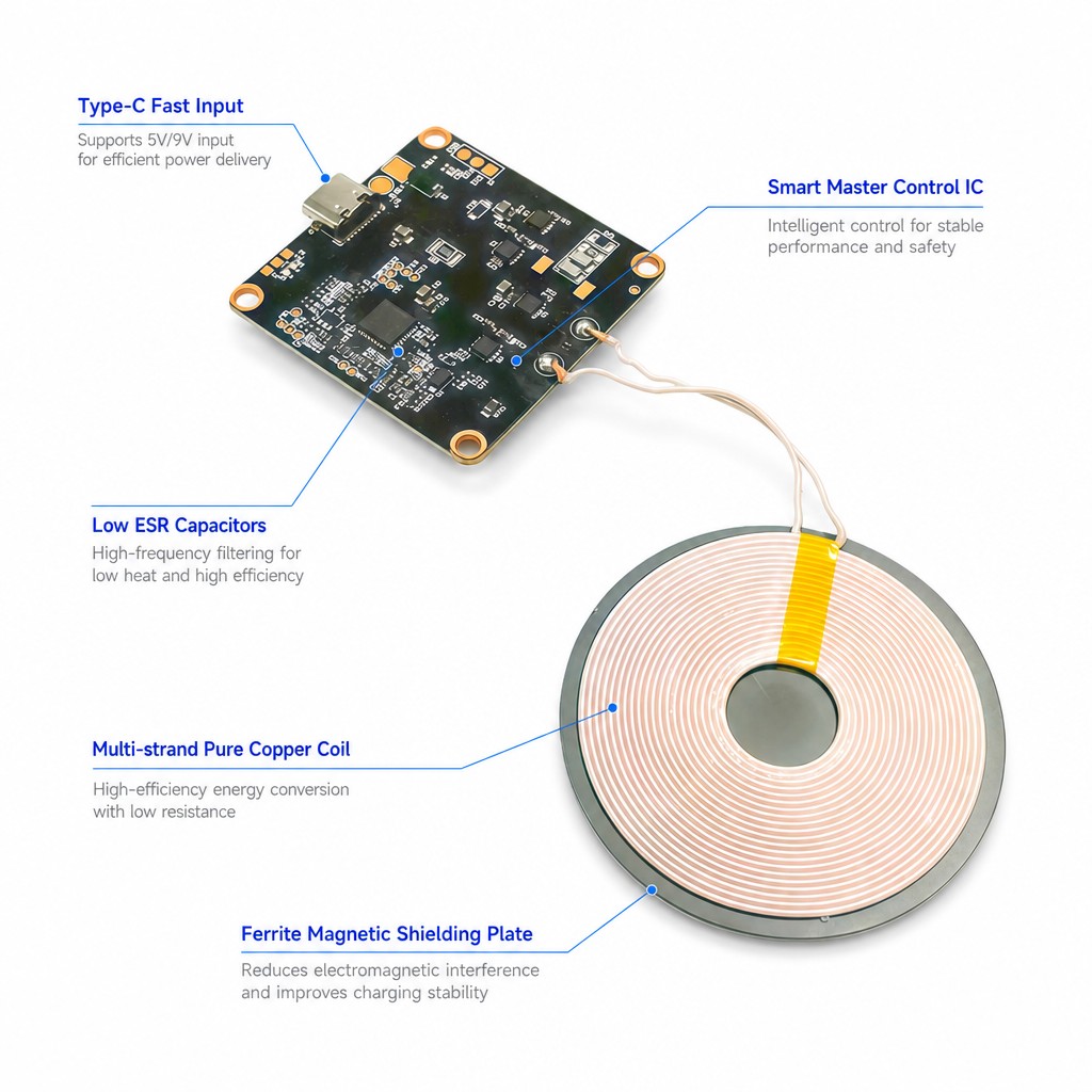
Qi wireless charging transmitter module: planar multi-strand copper coil on a ferrite shield plate, joined by short leads to a control board with USB Type-C input, smart control IC and low ESR capacitors. 15 W maximum output, above 90 percent convers
- Output power
- 15 W maximum
- Fast charge profiles
- 15 W, 30 W, 50 W
- Input at the connector
- 5 V and 9 V
Phone:+86 13554723725
Email:rhea@zxycoil.com
Description
1. Product Name
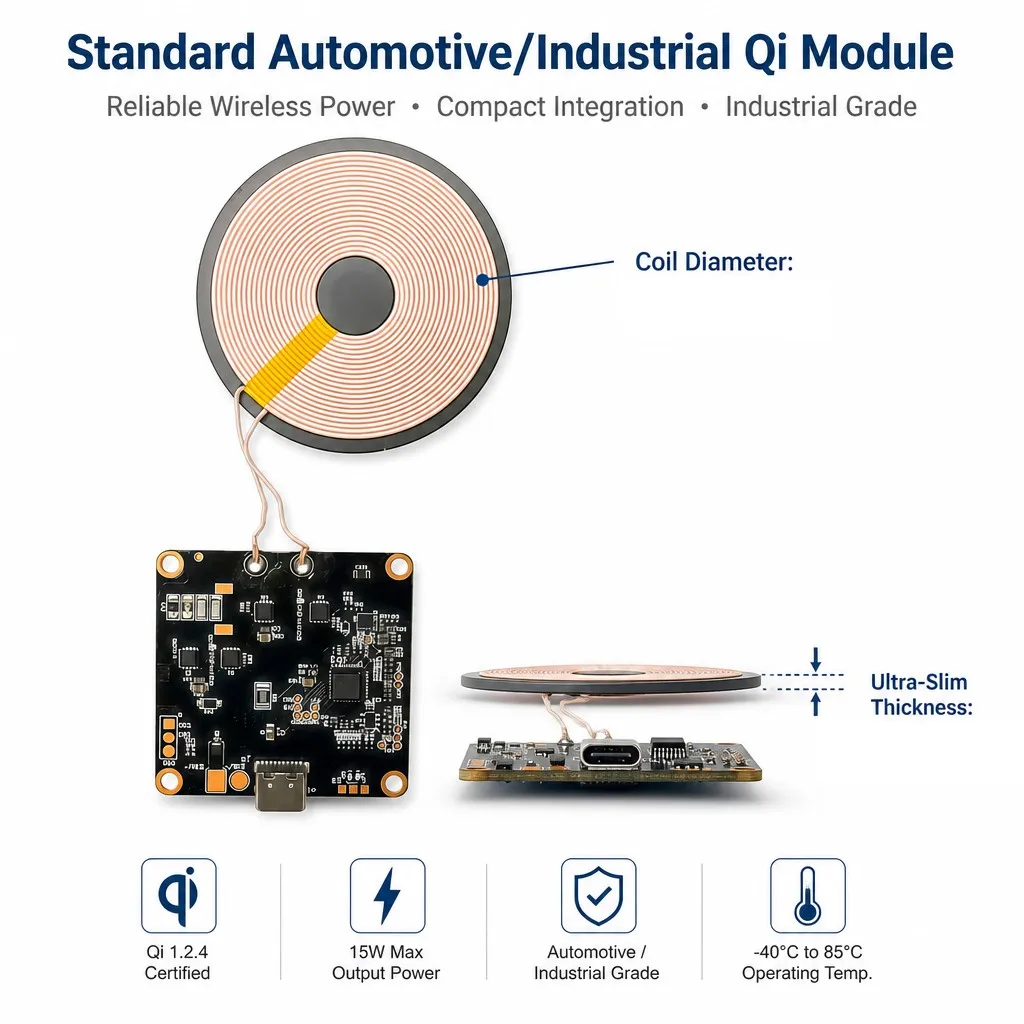
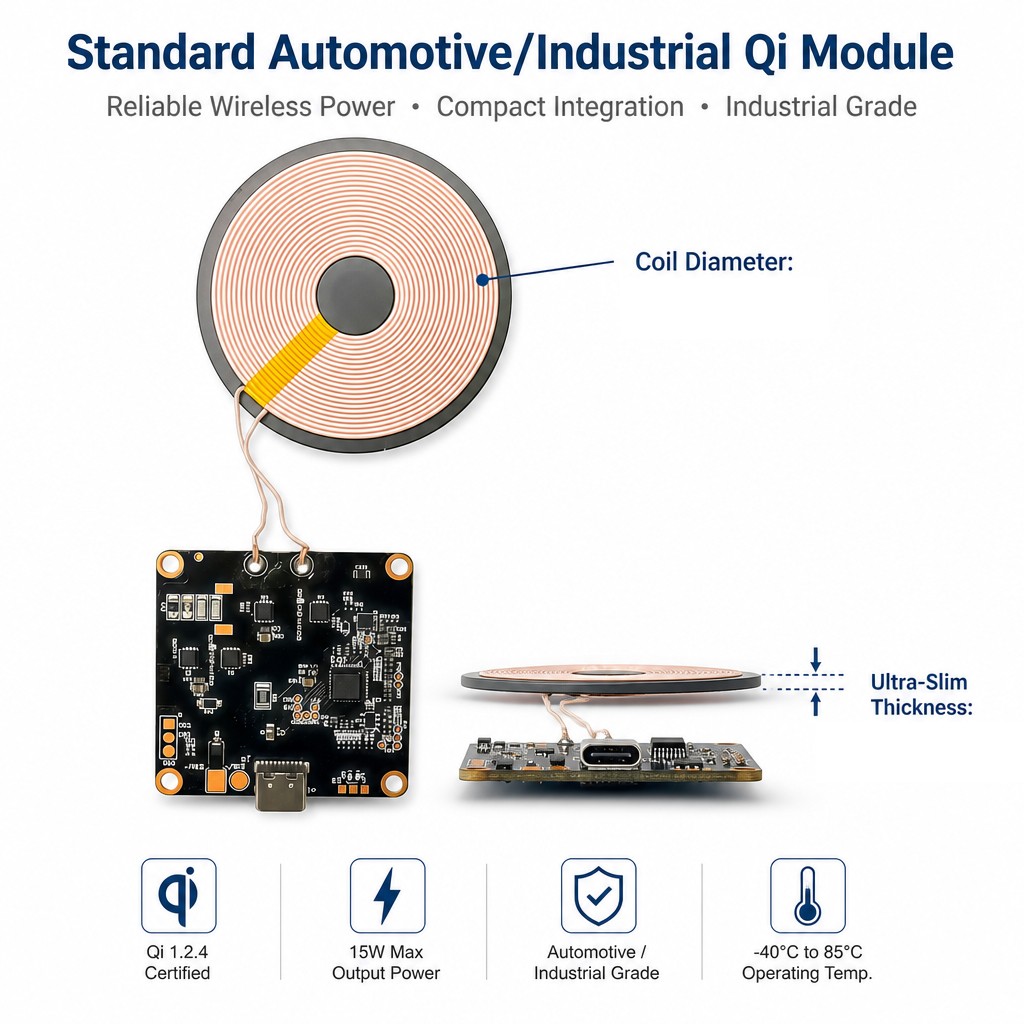
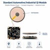
There is no model or part number on any of the eleven panels. The module is identified by what it is: a Qi wireless charging transmitter, coil plus control board, Type-C input, 15 W class. The two callouts that would fix its geometry, coil diameter and thickness, are printed on the overview panel with arrows and no value against either; only the 2.19 mm profile appears elsewhere. For a bill of materials the description, the photograph and the coil are what the part has to be ordered by until a code is issued.
What the panels call it varies: a standard automotive and industrial Qi module, a Qi wireless charging transmitter module, and a wireless power module. Those are one object described for three audiences. It is not a wound mains component in the sense the rest of this catalogue is: there is no primary on a mains supply and no isolation barrier, and the transformer action happens between two coils that are never electrically connected.
2. What It Does
Qi charging works by driving a coil with an alternating current and letting a second coil in the phone pick the field up. This module is the driving half. The board takes DC in on a Type-C connector, switches it into the coil through a bridge, and controls the field so that the receiver gets what it asks for; the receiver signals back by shifting its own load, which the board sees as a change in coil current. The ferrite plate behind the coil closes the field on the back side, so the metal or the battery under the module is not heated and the coupling to the phone is not lost.
3. Construction
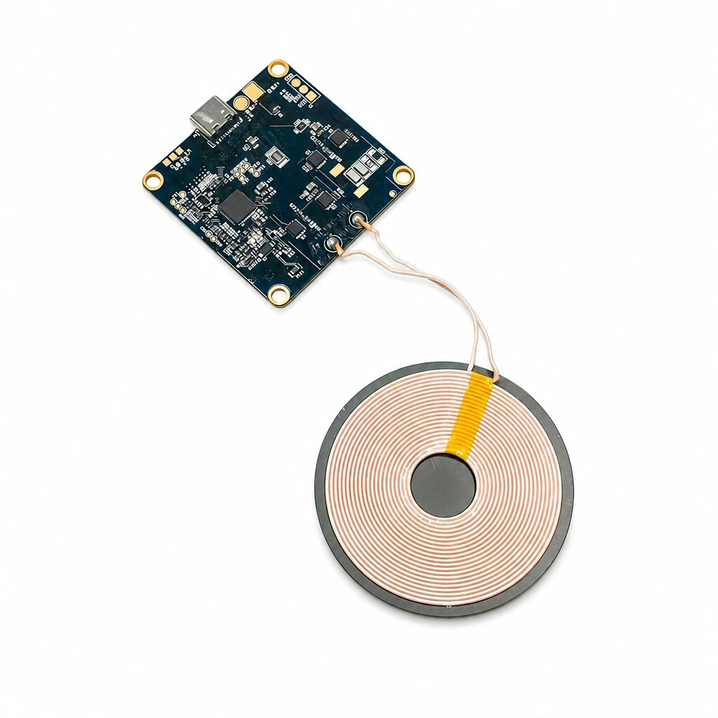
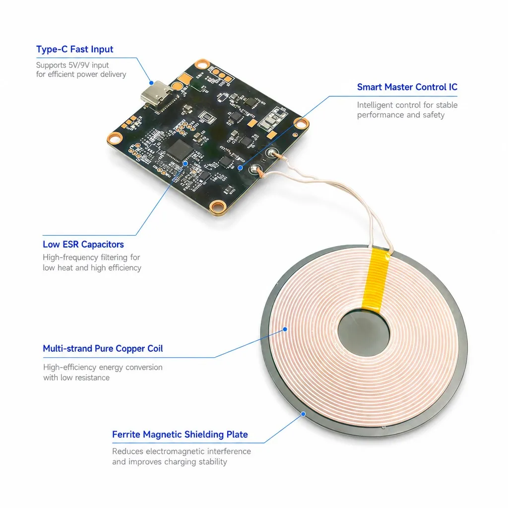
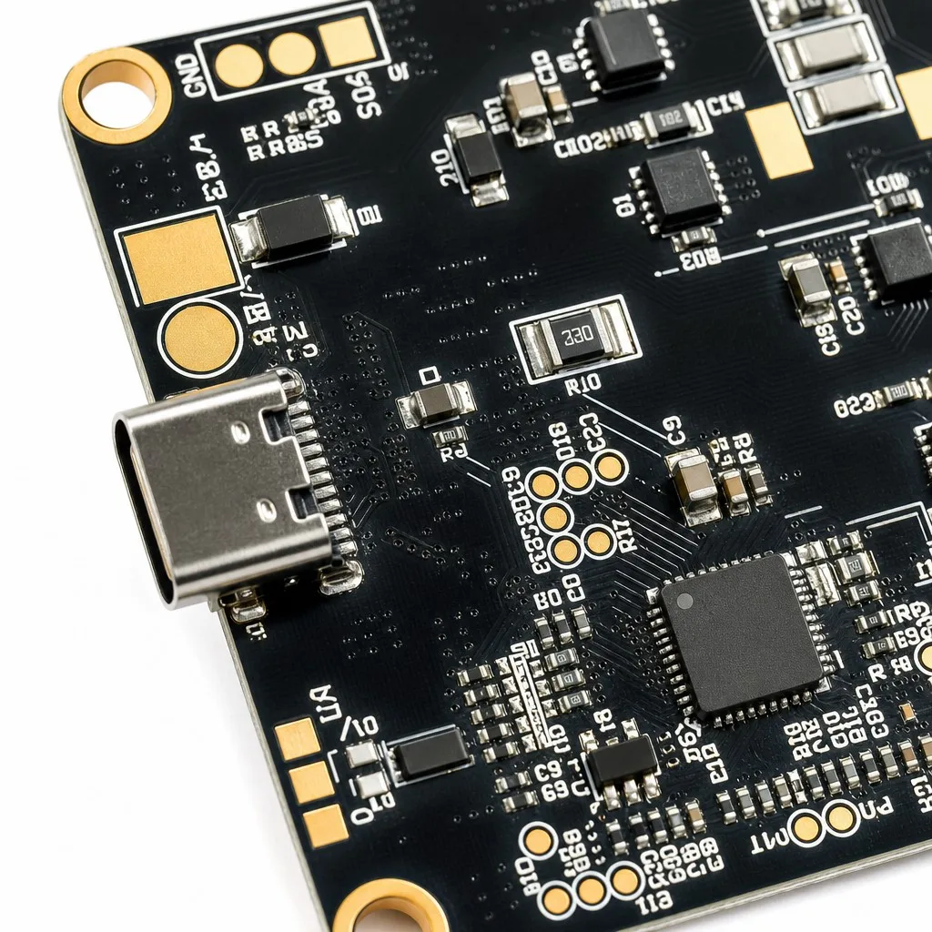
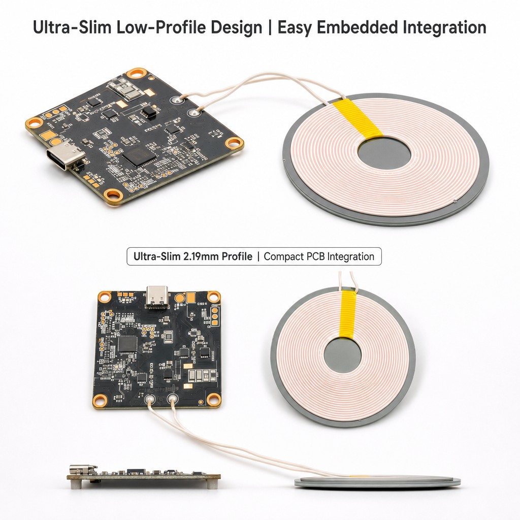
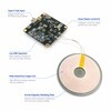
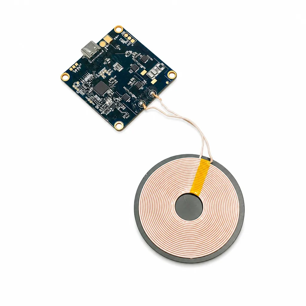
The module is two pieces joined by a pair of leads. The coil is wound flat from multi-strand enamelled copper, which the component panel calls out for low resistance and efficient energy conversion, and it sits on a ferrite plate that both shields the back and raises the inductance. The board carries the smart control IC at its centre, the driving bridge, a bank of low ESR capacitors for high frequency filtering, a Type-C receptacle at one edge and four plated mounting holes at the corners. Groups of gold pads and test points are broken out on the board and are visible in the close-up, marked with signal names, but what they do is not described anywhere in the material.
4. Coil, Shielding and Board
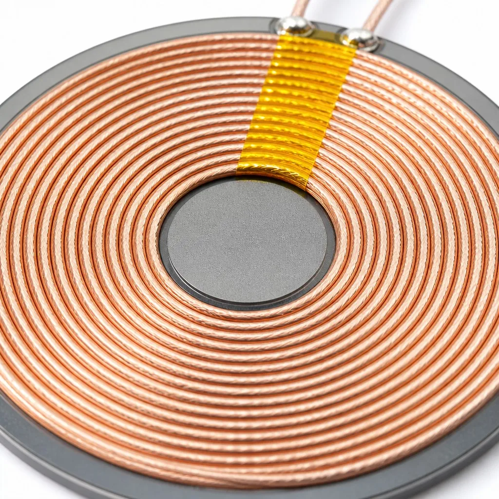
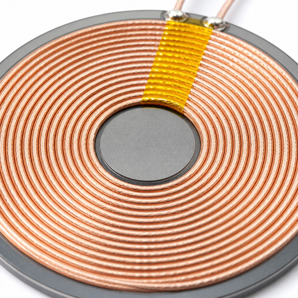
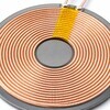
The close-up shows what the coil actually is: a flat spiral of closely spaced turns of multi-strand copper, ending in two soldered tails that go to the board. The individual strands are visible in the enamel, which is why the panel describes the winding as multi-strand rather than solid wire. A strip of yellow tape bridges the winding where the tails leave, holding the coil down and insulating the crossover. The ferrite plate underneath is a dark disc slightly larger than the winding, and it is the reason the module can be mounted against metal.
5. Electrical Specifications
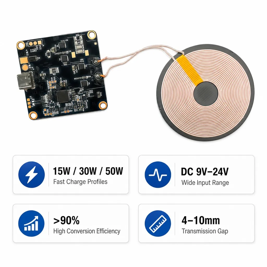
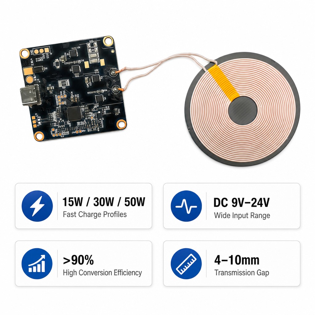
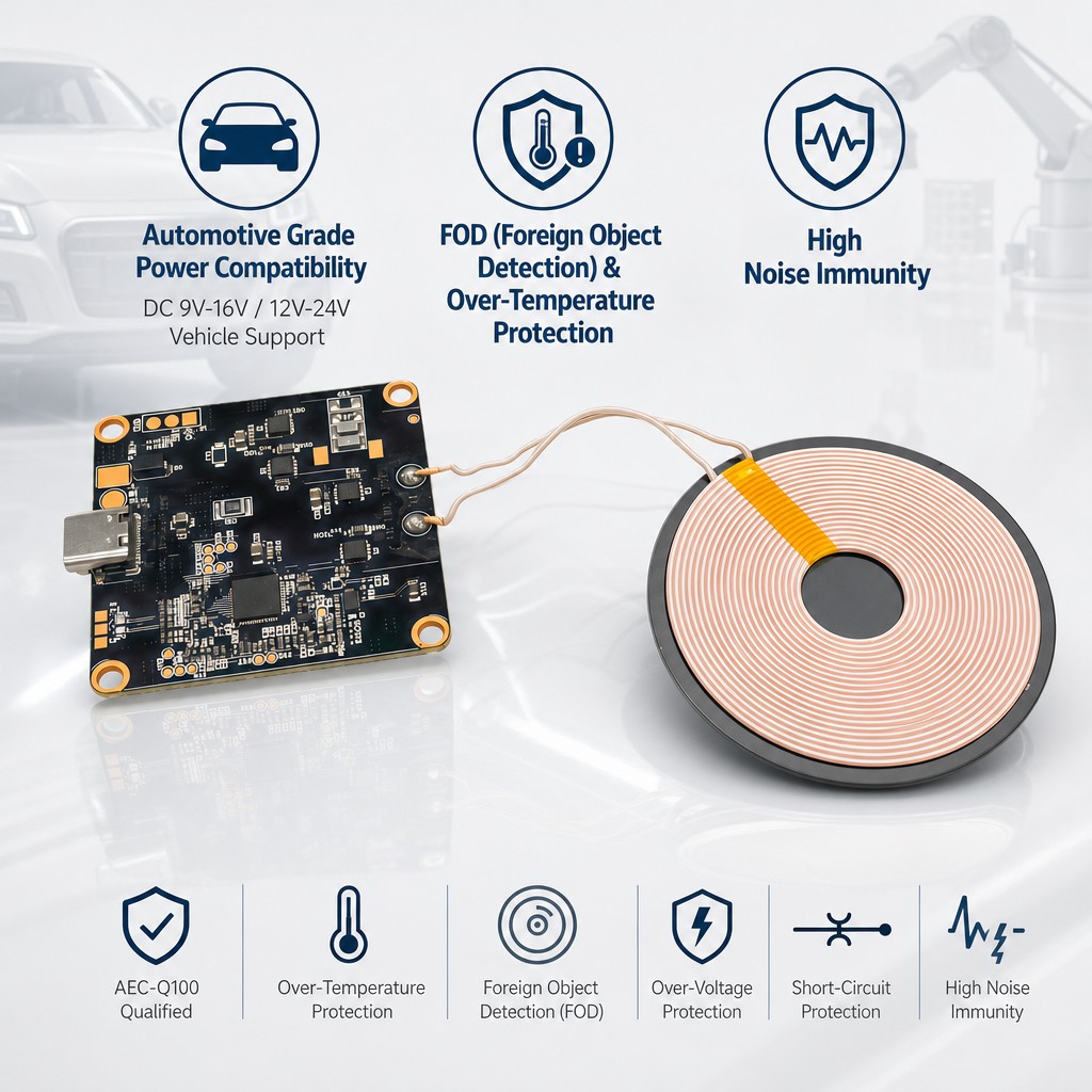
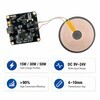
The electrical offer is short and it does not agree with itself. The overview badge gives 15 W maximum output. The feature panel gives fast charge profiles of 15 W, 30 W and 50 W. Input is stated three ways: 9 V to 24 V on the feature panel, 5 V and 9 V at the Type-C connector, and 9 V to 16 V or 12 V to 24 V on the automotive panel. Efficiency is above 90 percent with no load, voltage or temperature against it. The operating range is minus 40 to 85 degrees C.
5.1 The published set, panel by panel
| Parameter | Value | Note |
|---|---|---|
| Output power | 15 W maximum | Overview badge; a feature panel lists 30 W and 50 W profiles |
| Fast charge profiles | 15 W, 30 W, 50 W | How these relate to the 15 W maximum is not stated |
| Input at the connector | 5 V and 9 V | Type-C callout |
| Input range | DC 9 V to 24 V | Wide input range panel |
| Vehicle input | DC 9 V to 16 V, 12 V to 24 V | Automotive panel, two ranges in one line |
| Conversion efficiency | above 90 percent | No load, gap or temperature given |
| Transmission gap | 4 mm to 10 mm | Coil to receiver coil |
| Operating temperature | minus 40 to 85 degrees C | Overview badge |
| Qi version | 1.2.4 and v1.3 | Two different values on two panels |
| Coil diameter | Not stated | Callout drawn on the overview panel with no value |
6. Performance and Profile
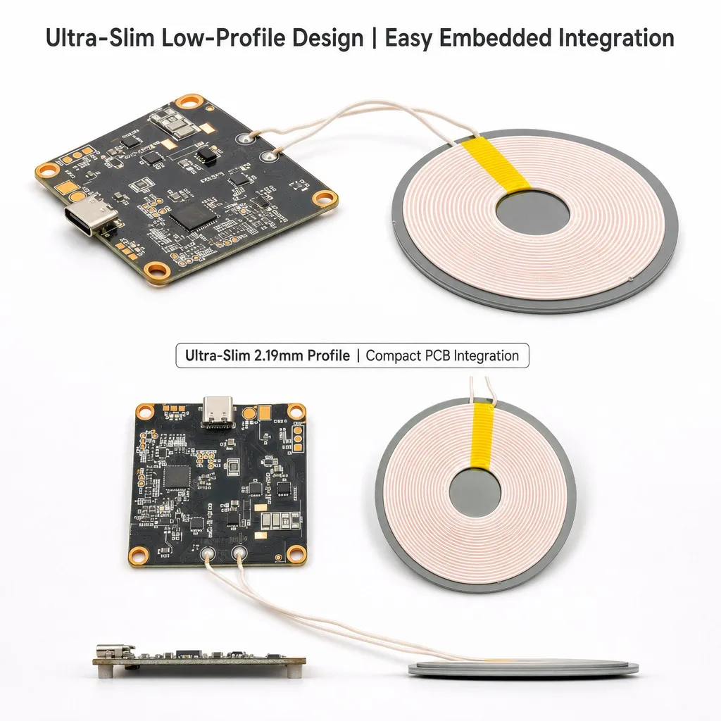
Three performance claims are made without conditions. Conversion efficiency is above 90 percent. The transmission gap is 4 mm to 10 mm. The profile is 2.19 mm with the board and the coil laid flat. The efficiency figure is the one to test: it depends on the gap, the alignment, the load and the receiver, and none of those is stated. The gap range is the useful number for a mechanical design, because it sets how thick the surface over the coil can be.
7. Automotive Qualification
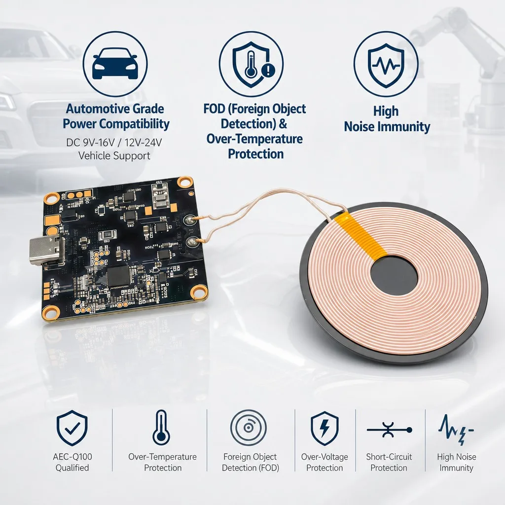
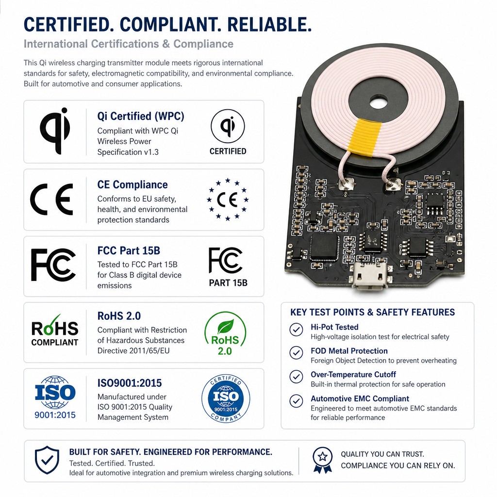
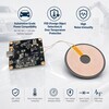
The automotive panel is a list of qualifications rather than a second specification. AEC-Q100 is named, which is an integrated circuit qualification rather than a module one, and the input is restated as 9 V to 16 V and 12 V to 24 V for vehicle support. Protection is listed as foreign object detection, over-temperature, over-voltage and short-circuit, with high noise immunity claimed separately. The compliance panel adds hi-pot tested, foreign object metal protection, over-temperature cutoff and automotive EMC conformance, again without a test report.
8. Integration
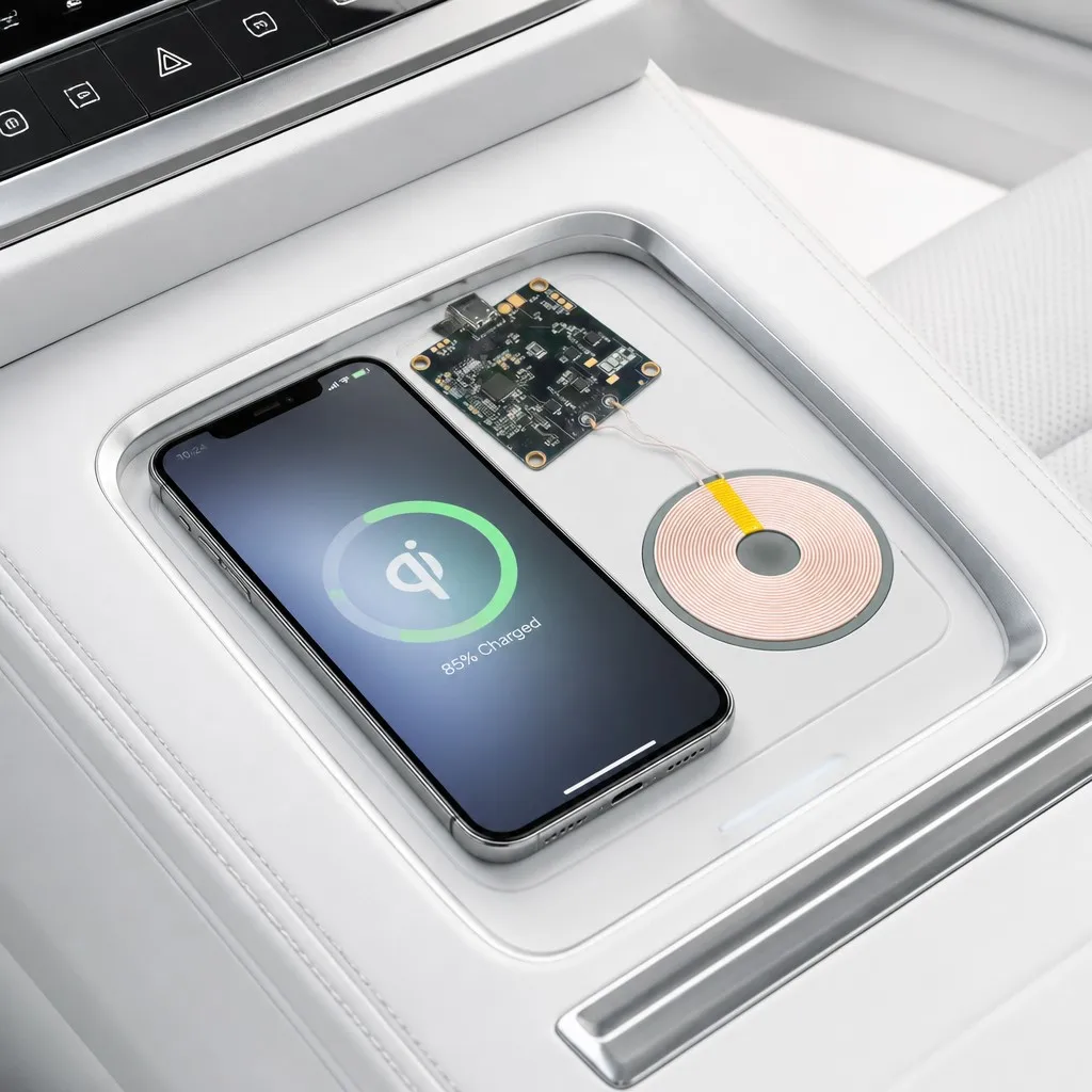
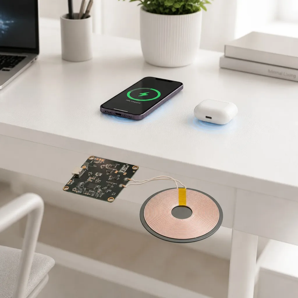
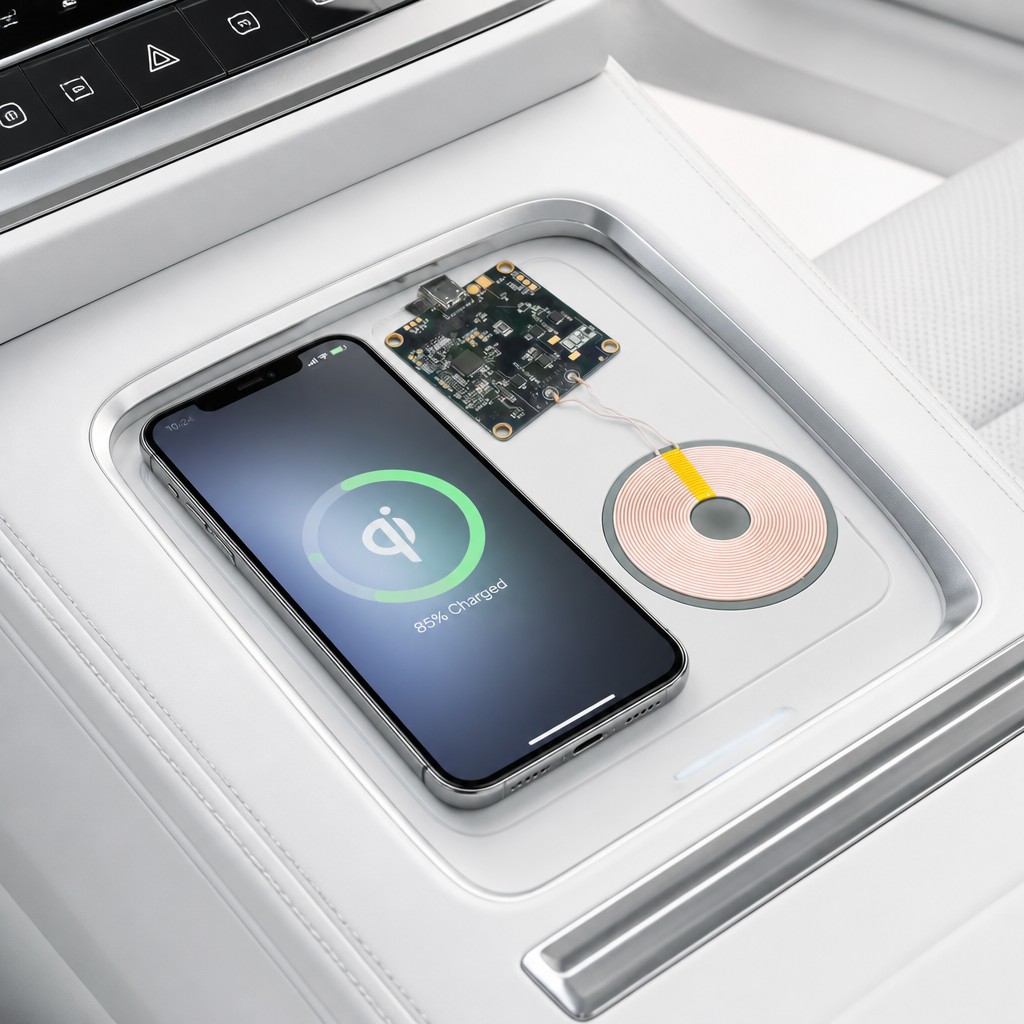
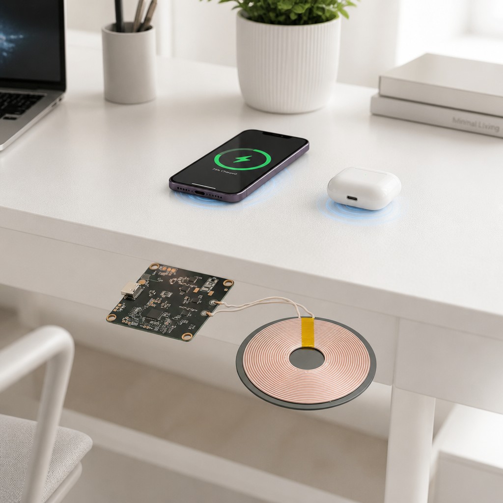
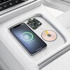
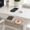
Two images show the integration the module is sold for. In a vehicle the coil and the board sit under a console tray and the phone charges on the surface above them. On a desk they sit under the top with the phone and a case of earbuds charging on it. Both are renders of the same layout: board to one side, coil to the other, a short pair of leads between them, nothing else visible. That is the practical constraint on the design, because the board and the coil need adjacent real estate and a surface thin enough to leave the gap inside its range.
9. Quality and Compliance
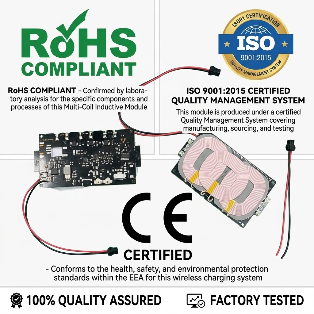
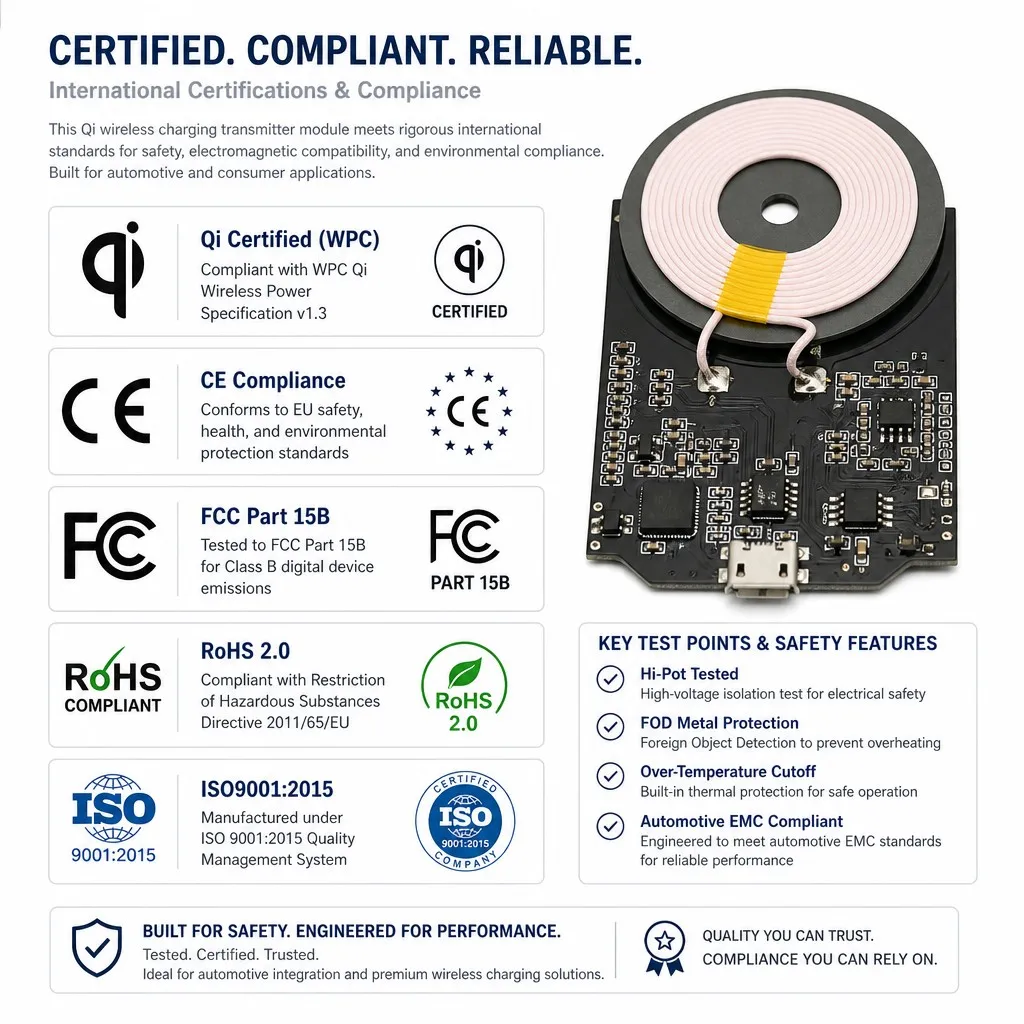
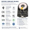
The compliance panel is the longest in the set and it is a list of marks. Qi under WPC, given as a certificate; CE for EU safety, health and environmental standards; FCC Part 15B for Class B digital device emissions; RoHS 2.0 under Directive 2011/65/EU; and ISO 9001:2015 for the quality system, which belongs to the factory rather than to the module. Hi-pot tested, foreign object metal protection, over-temperature cutoff and automotive EMC are listed as test points. No certificate number, report number or standards edition is printed against any of them, and the Qi version itself is given as v1.3 here and 1.2.4 on the overview badge.
| Item | Statement | Note |
|---|---|---|
| Qi | WPC Qi certificate shown | Version given as 1.2.4 and as v1.3 |
| CE | Mark shown | No certificate number |
| FCC | Part 15B, Class B emissions | No report number |
| RoHS | 2.0, Directive 2011/65/EU | No certificate number |
| ISO 9001 | 2015, quality management system | A factory system, not a module approval |
| AEC-Q100 | Qualification named | IC qualification, no report or grade given |
| Hi-Pot | Tested | Voltage not stated |
10. Feature
A coil and a board, nothing else. The whole module is the planar winding on its ferrite plate, the control board, and the pair of leads between them.
Type-C input. A USB Type-C receptacle on the board edge, quoted as 5 V and 9 V at the connector and as a 9 V to 24 V range on the feature panel.
Ferrite backed coil. A plate under the winding shields the back of the module, so it can be mounted against metal without loading the coil.
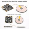
Thin enough to embed. A 2.19 mm profile with the board and the coil side by side, which is what allows the module to sit behind a panel or a desk top.
Protection listed. Foreign object detection, over-temperature, over-voltage and short-circuit protection are named on the automotive panel, with FOD metal protection repeated on the compliance panel.
Automotive orientation. AEC-Q100 named, automotive EMC and a 9 V to 16 V vehicle range restated on a panel of their own.
11. Advantage
It removes the connector from the product. The charging surface has no contacts to wear, no opening to seal and no orientation to get wrong.
One module behind a panel. Coil and control board are supplied as a set, so the mechanical design is a pocket and two leads rather than a connector cutout and a cable.
The ferrite plate is the enabler. Without it the module could not be fixed to a metal chassis; with it the field is kept on the phone side.
A width of surface thicknesses works. A 4 mm to 10 mm gap covers thin plastic, veneer and most console laminates, which is the range most products need.
Automotive paperwork is started. AEC-Q100 and automotive EMC are named, which is the point at which a vehicle programme can begin asking for reports.
12. Specifications
Values are transcribed from the supplier panels. Where a figure is absent the cell reads Not stated, and where two panels disagree both values are kept and the conflict is named in the note column rather than resolved here.
| Item | Specification | Note |
|---|---|---|
| Product | Qi wireless charging transmitter module | Coil and control board as a set |
| Coil | Multi-strand pure copper, planar | Turn count not stated |
| Shielding | Ferrite plate under the coil | Called out on the component panel |
| Board | Type-C input, control IC, low ESR capacitors | Component callouts |
| Input | 5 V and 9 V, or 9 V to 24 V | Three panels, see the note on the conflict |
| Output | 15 W maximum | Fast charge profiles also list 30 W and 50 W |
| Efficiency | above 90 percent | No test condition given |
| Gap | 4 mm to 10 mm | Coil to receiver coil |
| Profile | 2.19 mm | The only dimension published |
| Weight | Not stated | No figure published |
| Model | Not published | No part number on any panel |
13. Application
The uses below are the ones the material points at, with a note on why a module of this shape fits each. They describe where the part is sold, not a qualification of any one build.
Vehicle console charging. The coil under a tray lid, the board beside it, the phone dropped on the surface above.
Desk and furniture tops. The module under a 4 mm to 10 mm top, charging a phone and a case of earbuds above it without cutting the surface.
Public and hospitality furniture. Tables and counters where a sealed, contact free charging spot removes both the cutout and the cleaning problem.
Consumer audio and smart speakers. A charging spot on top of a powered product, using the same supply the product already has.
Industrial handhelds and instruments. Sealed enclosures that cannot take a connector, charged by placing the unit on a pad.
Embedded OEM designs. The coil and board used inside another product, with the gap and the pocket dimensioned around them.
14. Ordering
Send the application, the surface thickness and the load first, then the numbers. A usable enquiry states the input voltage available, the power the receiver needs, the gap the surface will give, the operating temperature and whether the build has to be automotive. Ask which of the published variants is being quoted, because the output power, the input range and the Qi version are each given two different ways on the panels, and ask for the coil diameter, the board outline, the mounting hole spacing, the lead length and the weight, none of which is published. Ask for the certificate and the test report for the standard the product has to meet before the design is fixed.
On compliance: the panel shows Qi under WPC, CE, FCC Part 15B, RoHS 2.0 and ISO 9001:2015 and presents them as covering the module. No certificate number, report number or standards edition is reproduced with any of them, the Qi version is stated as v1.3 here and 1.2.4 on another panel, and ISO 9001 belongs to the factory rather than to the part. They are reported here as marks and declarations, not as verified approvals. A wireless power transmitter is regulated on emissions and on exposure, so ask for the reports that go with the marks.
Brand / manufacturer: ZXY, Shenzhen Zhixiangyuan Electronics Co., Ltd. http://www.zxycoil.com
Specifications
| Output power | 15 W maximum |
|---|---|
| Fast charge profiles | 15 W, 30 W, 50 W |
| Input at the connector | 5 V and 9 V |
| Input range | DC 9 V to 24 V |
| Vehicle input | DC 9 V to 16 V, 12 V to 24 V |
| Conversion efficiency | above 90 percent |
| Transmission gap | 4 mm to 10 mm |
| Operating temperature | minus 40 to 85 degrees C |
| Qi version | 1.2.4 and v1.3 |
| Coil diameter | Not stated |
| Item | Specification |
| Qi | WPC Qi certificate shown |
| CE | Mark shown |
| FCC | Part 15B, Class B emissions |
| RoHS | 2.0, Directive 2011/65/EU |
| ISO 9001 | 2015, quality management system |
| AEC-Q100 | Qualification named |
| Hi-Pot | Tested |
| Product | Qi wireless charging transmitter module |
| Coil | Multi-strand pure copper, planar |
| Shielding | Ferrite plate under the coil |
| Board | Type-C input, control IC, low ESR capacitors |
| Input | 5 V and 9 V, or 9 V to 24 V |
| Output | 15 W maximum |
| Efficiency | above 90 percent |
| Gap | 4 mm to 10 mm |
| Profile | 2.19 mm |
| Weight | Not stated |
| Model | Not published |
Only supplied parameters are shown. Please confirm any unlisted electrical performance, test conditions, tolerances and customization options with our engineers. The final specification sheet takes precedence.
Product Images & Drawings
View the available product images and drawings below. Click to open the original. Customized products are subject to the agreed specifications and drawings.
Downloads
No specification sheet has been uploaded for this model yet. Use the inquiry form below to request parameters, dimension drawings or sample information.
Selection & Customization Requirements
To help confirm a suitable model and specification, please provide:
- Your equipment, application, operating environment and temperature range.
- As applicable: inductance, turns ratio or impedance, operating frequency, voltage, current and insulation requirements.
- Size limits, mounting method, pin spacing, and any existing drawings or reference samples.
- Sample quantity, estimated order volume and desired delivery date.
Frequently Asked Questions
Common procurement questions about 15W Qi Wireless Charging Transmitter Module Type-C Input 4-10mm Gap Ultra-Slim Coil and Control Board.
What is 15W Qi Wireless Charging Transmitter Module Type-C Input 4-10mm Gap Ultra-Slim Coil and Control Board?
Qi wireless charging transmitter module: planar multi-strand copper coil on a ferrite shield plate, joined by short leads to a control board with USB Type-C input, smart control IC and low ESR capacitors. 15 W maximum output, above 90 percent convers
Can 15W Qi Wireless Charging Transmitter Module Type-C Input 4-10mm Gap Ultra-Slim Coil and Control Board be customized to our specifications?
Yes. Shenzhen ZhiXiangyuan Electronics Co., Ltd. provides OEM/ODM services. Inductance, turns ratio, current rating, core material, size and terminal style can all be customized according to your drawings or samples.
What is the MOQ and lead time for 15W Qi Wireless Charging Transmitter Module Type-C Input 4-10mm Gap Ultra-Slim Coil and Control Board?
MOQ is negotiable based on the specific model and order quantity. Typical lead time is 1-3 weeks for standard items and 2-4 weeks for customized orders. Contact our sales team for an exact quotation.
Do you provide samples of 15W Qi Wireless Charging Transmitter Module Type-C Input 4-10mm Gap Ultra-Slim Coil and Control Board?
Yes, samples are available for evaluation before bulk orders. Please send us your requirements and shipping details to request samples.
What is the model number of this product?
The model number is 15W Qi TX Module. Custom model numbers can be assigned for OEM orders.
Send Us a Message
Tell us your requirements and our engineers will reply within 24 hours.
Related Products