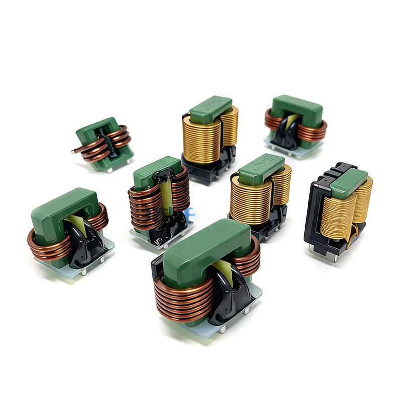
In various switching power supply topologies such as Buck, Boost, and Buck-Boost, the power inductor plays the core role of energy storage, filtering, and current smoothing. Though simple in structure, it is a critical component that determines the efficiency, ripple, and reliability of the power supply. This article focuses on the three key parameters—saturation current, DC resistance (DCR), and temperature rise current—and outlines the working principles and selection points of power inductors.
1. The Role of Power Inductors in Switching Power Supplies
The basic function of a power inductor is energy storage and freewheeling. During the switch-on period, the inductor stores electrical energy in the form of a magnetic field, and the current rises linearly. During the switch-off period, the inductor releases energy through the freewheeling diode or synchronous rectifier to maintain continuous load current. It is this "charge-discharge" cycle that enables the switching power supply to efficiently perform voltage conversion and regulation.
Meanwhile, the inductor, together with the output capacitor, forms an LC filter that smooths the switching waveform and suppresses output ripple. The inductance value directly affects the ripple current: higher inductance means lower ripple but slower dynamic response and larger size. Therefore, the inductance must be a trade-off among ripple, response speed, and size.
2. Three Core Parameters: Isat, Irms, and DCR
When selecting a power inductor, the following three parameters must all be satisfied—failure of any one can lead to power supply malfunction:
| Parameter | Definition | Consequence of Exceeding Limit |
|---|---|---|
| Saturation Current (Isat) | The current at which inductance drops to a specified ratio (e.g., -30%) | Sudden inductance drop, ripple surge, efficiency degradation, or even burnout |
| Temperature Rise Current (Irms) | The continuous current that raises device temperature to a specified value (e.g., 40°C) | Overheating, shortened lifespan, degraded reliability |
| DC Resistance (DCR) | The DC resistance of the coil | Higher DCR leads to greater copper loss, lower efficiency, and more severe heating |
In engineering practice, the smaller value of Isat and Irms is typically taken as the rated current limit, with sufficient margin reserved for peak currents and high-temperature conditions. Low DCR is a direct means of improving efficiency, especially critical in low-voltage, high-current CPU/GPU power delivery and automotive power supplies.
3. Common Structures and Core Materials
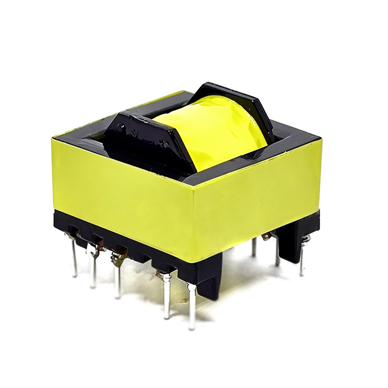
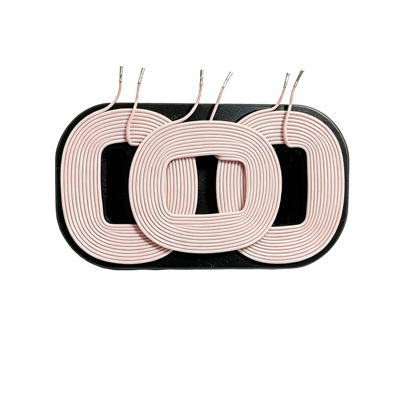
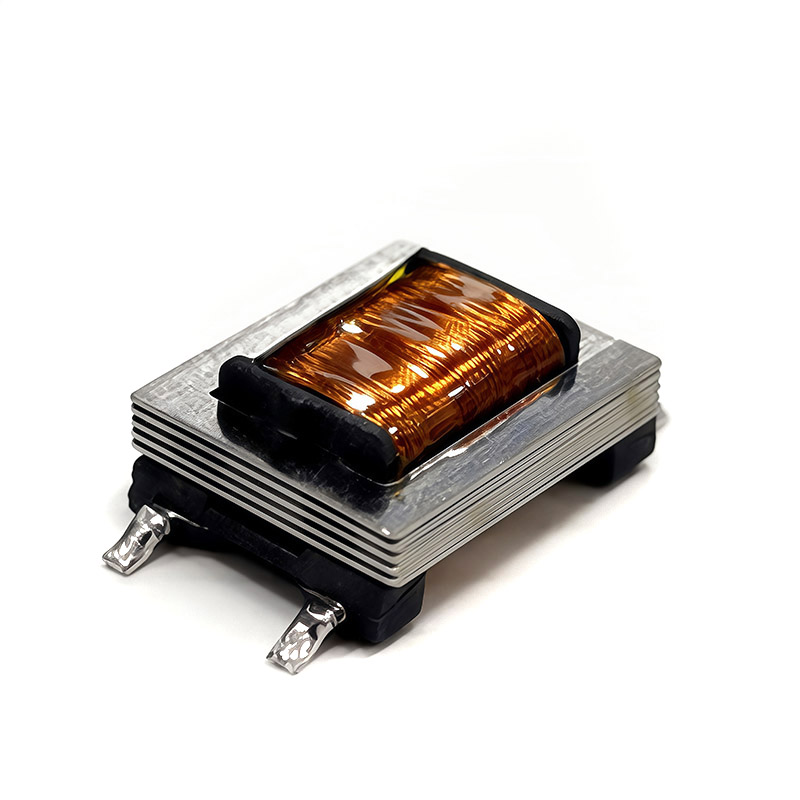
Power inductors can be classified by structure and core material into several types, each suited to different applications:
- Molded inductors: The core and coil are pressed as one unit, offering good shielding, low DCR, and strong anti-saturation capability. Widely used in smartphones, graphics cards, and server power supplies. See Molded Inductor Series.
- Toroidal inductors: With a closed magnetic path, low leakage flux, and high efficiency, they are commonly used in high-power and EMI-sensitive applications. See Toroidal Inductor Series.
- Rod/bar core inductors: Simple structure and low cost, suitable for low-to-medium power applications where size is less critical.
- Common-mode inductors: Primarily used to suppress common-mode interference and are core components in EMI filtering.
Regarding core materials, ferrite offers relatively high saturation flux density but is prone to saturation, with moderate cost. Alloy powder cores such as iron-silicon-aluminum and iron-silicon-chromium feature distributed air gaps, strong DC bias resistance, and a gradual saturation curve, making them more suitable for high-current applications.
4. Selection Points and Common Pitfalls
Proper power inductor selection should follow these steps: first, calculate the required inductance and ripple current based on the topology and switching frequency; then, verify Isat against the peak current and Irms against the RMS current; finally, choose a model with the lowest possible DCR and a suitable size and mounting style while meeting the current requirements.
- Pitfall 1: Considering only inductance and ignoring saturation current. The inductance may be adequate, but if Isat is insufficient, the inductance collapses under high current, causing immediate power supply failure.
- Pitfall 2: Overlooking temperature rise and heat dissipation. In enclosed spaces, Irms must be derated; otherwise, prolonged overheating shortens service life.
- Pitfall 3: Blindly pursuing small size. Size reduction is often accompanied by lower Isat/Irms, which must be balanced against electrical performance.
Zhi Xiang Yuan Electronics can provide customized services ranging from core material selection, winding design, to batch consistency control, based on the customer's power topology, switching frequency, input/output specifications, and space constraints—helping power supplies achieve an optimal balance among efficiency, temperature rise, and cost.
FAQ
Q1: Should I prioritize saturation current (Isat) or temperature rise current (Irms)?
Both must be satisfied. The actual rated current is the smaller of the two, with margin reserved. Isat addresses whether the core saturates (inductance collapsing), while Irms addresses whether the heating is acceptable—they correspond to different failure modes.
Q2: Why are molded inductors preferred in high-end power supplies?
Molded inductors use alloy powder cores and a one-piece molding process, offering low DCR, high saturation current, excellent magnetic shielding, and compact size. These advantages allow them to balance high efficiency with low EMI, which is why they are widely used in high-end power supplies for smartphones, graphics cards, and servers.
Q3: How can losses and heating in power inductors be reduced?
Three approaches can be taken: choose low-DCR windings with thicker wire or flat wire, use alloy powder core materials with strong DC bias resistance, and optimize the heat dissipation path and mounting position in the structure. Derating the rated current is also necessary in some cases.
Recommended Reading