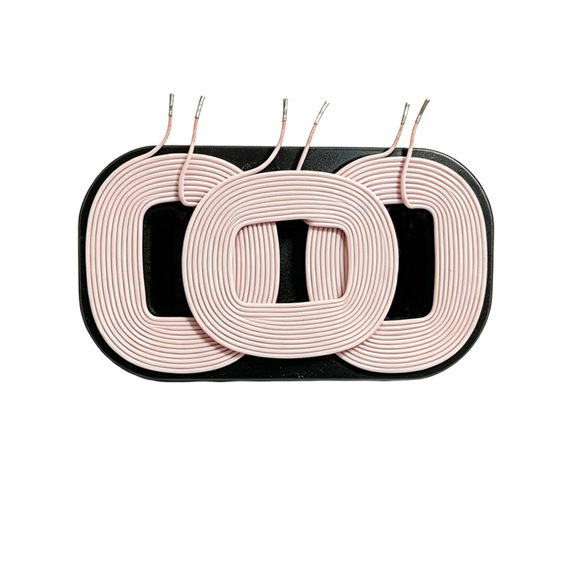
From smartphones and earbuds to electric toothbrushes and in-car chargers, wireless charging is rapidly penetrating consumer electronics and the new energy vehicle sector. As the core magnetic component of a wireless charging system, the wireless charging coil directly determines charging efficiency, heat generation, and compatibility. This article focuses on three key aspects—the Qi standard, magnetic core materials, and heat control—to break down the technical essentials and selection approach for wireless charging coils.
1. Fundamentals of Wireless Charging and the Qi Standard
Mainstream wireless charging today is based on the magnetic induction coupling principle: the transmitter (Tx) coil is driven by a high-frequency alternating current to generate an alternating magnetic field, which induces an electromotive force in the receiver (Rx) coil, enabling contactless power transfer. The operating frequency typically ranges from 100–205 kHz.
Qi is the industry standard established by the Wireless Power Consortium (WPC), specifying communication protocols, power levels, and interoperability requirements between transmitters and receivers. From the early 5W (BPP) to today's 15W (EPP) and even higher power levels, the Qi standard continues to evolve. Choosing coils and core assemblies that comply with Qi specifications is a prerequisite for cross-brand compatibility and certification. Zhixiangyuan Electronics offers wireless charging coils customizable to Qi standard parameters, covering both Tx transmitter coils and Rx receiver coils.
2. Magnetic Core Materials: Why the Shielding Sheet Is Indispensable
The magnetic shielding sheet (core) attached behind the coil is a critical material in a wireless charging module. Its role is to guide the magnetic flux, improve the coupling coefficient, and shield magnetic field leakage toward metallic components behind it (such as batteries or shielding cans), preventing eddy current heating. Three common material types are used:
| Core Material | Characteristics | Typical Applications |
|---|---|---|
| Ferrite | Moderate permeability, low cost, brittle | Low-to-mid-power phones, general consumer electronics |
| Nanocrystalline | High permeability, low loss, flexible | High-power, ultra-thin modules |
| Amorphous/Fe-Si-Al composite | High saturation flux density, good DC bias resistance | Automotive, high-power fast charging |
The higher the permeability, the stronger the coupling and the higher the transmission efficiency—but excessively high permeability makes saturation more likely under DC bias or in the presence of metal foreign objects. In practice, material selection requires a balance between efficiency, thickness, cost, and anti-saturation capability.
3. Coil Construction: Litz Wire, Turns, and Geometry
Transmitter coils are typically wound with Litz wire, which consists of multiple individually insulated fine copper strands twisted together. This construction significantly mitigates skin effect and proximity effect at high frequencies, reducing AC resistance and losses. The coil's number of turns, inner/outer diameter, wire gauge, and winding method collectively determine its inductance and quality factor Q.
- Inductance: Qi systems specify defined ranges for Tx/Rx inductance; excessive deviation leads to resonant mismatch and a sharp drop in efficiency.
- Q factor: A higher quality factor means lower losses and higher transmission efficiency, but it must be precisely matched with the compensation capacitor.
- Geometry: Dimensions must align with the device's internal space and alignment tolerance; automotive applications also need to account for vibration and thermal cycling.
4. Heat Control and Efficiency Optimization
Heat is the "number one enemy" of the wireless charging experience. Coil heating primarily comes from copper loss (coil resistance × current squared) and core loss; additionally, metal foreign objects (FOD) and misalignment introduce extra eddy-current heat. Effective heat control measures include:
- Selecting Litz wire with an appropriate strand diameter to reduce high-frequency AC resistance;
- Optimizing magnetic core material and thickness for minimal loss at the operating frequency;
- Precisely matching the resonant capacitor so the system operates at the optimal resonance point;
- Designing a proper heat dissipation structure and thermal path, adding temperature feedback and power derating protection when necessary.
In mass production, consistency of coil inductance and Q value is especially critical. Zhixiangyuan Electronics ensures stable batch-to-batch parameters through standardized winding processes and 100% inspection, helping customers pass Qi certification smoothly and reduce heat-related complaints.
FAQ
Q1: Can the transmitter and receiver coils be used interchangeably?
Generally, no. Tx coils typically have fewer turns, thicker wire, and higher power ratings, while Rx coils are thinner and better suited to the device's internal space. The inductance and construction of each are designed for their respective roles, so they must be selected separately.
Q2: Why does wireless charging generate noticeable heat?
Heat comes from copper loss in the coil, core loss, eddy currents in metal foreign objects, and misalignment. Using low-loss Litz wire and appropriate magnetic cores, precise resonant matching, and adding foreign object detection (FOD) and temperature control can significantly reduce heat.
Q3: What parameters should I provide when customizing a wireless charging coil?
It is recommended to provide: target power level (e.g., 5W/15W), operating frequency, Tx or Rx application, inductance and Q value range, coil inner/outer diameter and thickness, preferred core material, and the application environment (phone/automotive/wearable). A reference sample or specification sheet is even better.
Recommended Reading